
Die shops across North America understand that their survival depends on their efficiency, especially when it comes to their tooling design workflow. Outsourcing has moved a lot of design work offshore, and shops need to be more productive than ever to provide value. That’s why our team at LTS has drawn on decades of industry experience to highlight the top four productivity killers in die design—and what your shop can do about them.
Tedious BOM updates
The first area where we see shops hemorrhaging time and money is the editing of their tooling BOMs. Companies using basic CAD systems need to perform a lot of manual work when attributing a die or transfer with details like stock size, material, and other part attributes. When a designer begins a new project, they need to enter all this information again instead of easily pulling it from a library. This creates major inefficiencies in BOM creation and introduces more opportunity for error.
“Companies that are editing their BOMs manually are spending about 60% longer on this activity than they need to be,” says Reuben Greenhous, a veteran of the die industry who has designed for several top shops over three decades. “This is definitely one of the areas where they’re losing the most time, and it’s not all that fun for the person updating the BOMs either.”
Shaky collision checking
Collision checking is an essential part of the die design process. Finding collisions and interferences after machining sets back your project timeline and hurts your reputation with customers.
Many companies perform static collision checking with basic CAD software, but this only catches the collisions that occur when the die is in the closed position. There are many more interferences associated with motion curves and timing that are only caught once the die is assembled and dry entered on the bench.
Catching an error after machining a tool is extremely costly. But what’s also costly is having a design team try to figure out where these hidden collisions are by pouring more time and effort into the review process. This puts the company in a catch-22, where they either spend too much time validating the die or too much time fixing the die after finding a collision. In short, die design teams need a way to be careful faster.
Overly manual surfacing
Surfacing can be a massive time-suck for companies designing their dies with basic CAD packages. Trying to click on edges and manually modify complex die surfaces is a lesson in futility, hurting design timelines and making designers miserable. Basic CAD software at a basic CAD price point doesn’t have the computing horsepower to automate the design and modification of complex surfaces. This leaves the user with the crummy task of trying to make things right with manual clicks.
Unlinked geometries
The geometries of a die are a sensitive ecosystem. When a body, face, curve, or sketch changes, so must every geometry that interacts with it. For example, if you need to make a trim change in a die, you don’t want to go through the process of manually updating the punch, punch holder, die steel, lower subplate and lower die set that interact with that trim line change. And if you’re using a basic CAD tool, that means seeking out all those individual geometries and manually updating them to reflect the update you made to the trim line. Again, this is a major drain on time and a threat to the quality of the final die design, as it introduces more sources of possible error.
What can be done?
We’ve worked with countless die shops to overcome these productivity killers and are happy to mention some of the solutions here. Let’s take them one by one.
Accelerating BOM creation
Many companies might not realize that the speed of creating and updating their BOMs depends on how much their design software has been tailored to the die industry. Our team at LTS works with many companies using the Mach 3 Die Design package from Siemens NX CAD software to automate this process and perform BOM-related activities 60% faster than with other tools.
For example, in the Siemens NX Die package, users can automate the attributing of dies to have stock size and materials pulled into their BOM from a library. They can also customize the BOM for faster and easier data entry, using a preferred internal company format and exporting according to customer requirements.
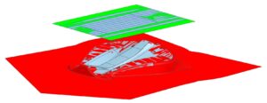
Faster, more reliable collision checking
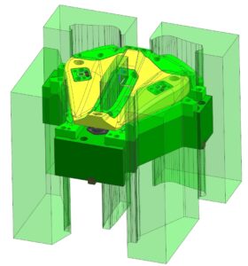
Companies that use dynamic collision checking have 100% success catching all interference conditions before a die is machined. This saves them time and money in two ways: by avoiding costly rework and by speeding up the validation process with greater confidence. That’s why the team at LTS has collaborated directly with die and transfer shops to create Dynmik Design for Die, the global standard for collision checking and motion simulation in die design.
Motion simulation and dynamic collision checking are an integral part of the design review process for any die shop. An added bonus is that Dynmik Design for Die can be used in design reviews with customers to increase confidence in the tool and/or transfer system they are receiving. Customers consistently report greater confidence in purchasing from die shops that can show them a 4D simulated tool prior to delivery. In short, dynamic 4D collision checking with Dynmik Design for Die helps companies be more careful faster.
Smarter surfacing
Of all the benefits that tooling customers gain from Siemens NX CAD software, advanced surfacing is always near the top. This is because the NX Mach 3 package can automate the creation and modification of complex surfaces in ways that other CAD solutions can’t. When companies evaluate NX for purchase, the surfacing features are often the point where users realize they’re dealing with a much more powerful solution than they’ve previously used. And our team at LTS has helped many shops take full advantage of these capabilities to create better tools faster.
Wave Geometry Linker
Companies that manually update associated geometries in their tools experience a major transformation when they start using Wave Geometry Linker. This tool in Siemens NX allows the designer to reference existing part geometry when designing a new part in existing assemblies. For example, if you need to make a trim change in a die, you can have NX automatically update the punch, punch holder, die steel, lower subplate and lower die set that interact with that trim line change. This level of premium design automation is another reason why tooling shops make the investment in NX CAD over more basic solutions and enjoy greater profitability in the long run.
Conclusion
At the end of the day, CAD software isn’t a commodity—it’s an investment. Choosing higher-quality, die-focused software isn’t always an easy call for a manager to make, but the alternative is the slow bleed of lost time and money that comes with using lower-cost, basic CAD packages.
We are proud to have a team of industry-experienced die design experts to help your die design team thrive in the global market. Please don’t hesitate to reach out to us chart your path to 50% greater productivity. We look forward to helping your company take its next step forward in digital industry.

